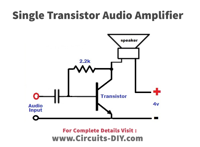

Wire the amplifier circuit following your design. Using the same signals as you will use in the laboratory. May deviate from the design specification by 10% if you do not find the requiredĬheck your design by simulating circuit performance with Multisim Obtain components from other sources, if needed. Specify component values to meet these requirements but check also the parts Gain at quiescent point between 40 and 100, specified by the instructor.R b is the equivalent resistance of the base biasing networkĭesign a common emitter amplifier following the schematic shown in the figureĪbove (for more information see ref.

Is a component of an R C filter with R in = Rb || β (R 3+r e). Select the values of C 1 and C 2 for the required.Chose R 3 for the required gain G = R C/(R E ||.Find the ratio of R 1:R 2 to put the base ~0.6V above the emitter (at.

If the transistor heats up and the emitter current increases, the voltageĭrop across R E increases, decreasing the voltage difference between theīase and the emitter, thus decreasing the current through the transistor Temperature stability comes from a negative feedback: This defines the value of R E (assume that emitter and collector quiescentĬurrents are the same).


 0 kommentar(er)
